Synchronous Decision Diagrams: a Data Structure for
Representing Finite Sequential Digital Functions
Jean Vuillemin
DMI, École normale supérieure
Algorithms Seminar
May 22, 2000
[summary by Philippe Dumas and Philippe
Flajolet]
A properly typeset version of this document is available in
postscript and in
pdf.
If some fonts do not look right on your screen, this might be
fixed by configuring your browser (see the documentation here).
Abstract
Binary Diagrams (BDD's) are an important way to represent
boolean functions, that is, combinational circuits. Vuillemin
proposes Synchronous Decision Diagrams (SDD's) that are capable of
representing all causal circuits with finite memory. The framework
provides a general basis for the analysis and synthesis of digital
circuits. On the mathematical side, it provides unexpected
connections between hardware design and the classical notion of
automatic sequences in number theory.
Researchers working in circuit theory are concerned with design (given
a function, how can it be realized efficiently?) and analysis (what
is the function computed by a given circuit?). This talk presents a
mathematical framework for the design and analysis of boolean
circuits, either combinational (i.e., without memory) or sequential
(i.e., with memory). It is superbly elegant as well as conceptually
simple. We shall start here with a review of Binary Decision Diagrams
(BDD's) that constitute a canonical way to represent boolean functions
and serve the purpose of a gentle introduction to the subject. Then,
we shall proceed with Synchronous Decision Diagrams (SDD's) that can
represent any type of circuit likely to be encountered in practice
(i.e., circuits with finite memory of the past whose output does not
depend on the future). Due to severe time constraints imposed by the
editor of the seminar proceedings,1 the authors of
this summary regret that they cannot do full justice to the work
presented and refer to the paper [8] for an
introduction to the main ideas.
1 Binary Decision Diagrams
Let B be the boolean domain B={0,1}. A boolean function
of n variables is a function from Bn into B. Such a
function may be specified by its truth table that is the sequence of
its values on its 2n possible inputs. Let Fn be the set of
n-ary functions and fn the corresponding cardinality.
Clearly, one has fn=22n, hence the identity
|
fn+1= 2 |
|
º |
æ
è |
2 |
|
ö
ø |
|
= |
( |
fn |
) |
|
.
|
Fn+1 ~ Fn×Fn.
Indeed any boolean function f(x1,...,xn,xn+1) with fÎFn+1
can be specified by a pair (f0,f1), where
f0ÎFn and f1ÎFn are ``specializations'' of f,
f0(x1,...,xn):=f(x1,...,xn,0),
f1(x1,...,xn):=f(x1,...,xn,1).
Consequently, when the decomposition is iterated,
any boolean function of n variables becomes representable as
a perfect binary tree, the
binary decision tree bdt(f),
whose height is n,
whose internal nodes correspond to partial specializations of f,
and whose external nodes are
either the constant function 0 or the constant function 1.
Observe that reading the B labels of
the extrenal nodes of bdt(f) from left to right
produces precisely
the truth table of f.
The binary decision diagram2 of f, bdd(f),
is then nothing but the directed acyclic graph (dag)
representation of this tree obtained in the usual way
by sharing repeated subtrees and representing them
only once. It is classically known that such a dag representation
of a tree of size N can always be
constructed in time O(N); see for instance [5]
for a discussion.
Here, one has N=2n for functions in Fn, so that
the sharing algorithm approach is of exponential time complexity when f is
given by its truth table or, equivalently,
by its tree bdt(f). In many cases,
fortunately, one can operate with polynomial time complexity.
Here is an example. Consider the adder function on three variables,
f(a,b,c)=aÅ b Å c.
We purposely refrain from operating with the truth-table description
of f in order to emphasize that BDD's are
directly accessible via a symbolic
calculus on boolean functions. Here, two ``subfunctions'' are first
obtained upon setting the variable c to either 0 or 1:
f0(a,b)=aÅ b, f1(a,b)=aÅ bÅ 1.
Next, specialize b, which yields here only two
(and not four!) distinct functions,
namely,
f00(a)=a, f10(a)=aÅ1 (with f01º f10
and f11º f00).
Finally, specialize a, which eventually
leads to a reduction to the two constant functions
f000()=0,
f010()=1 (with f100º f010
and f110º f000).
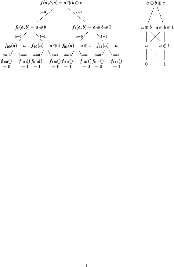
Figure 1:
The adder function,
f(
a,
b,
c)=
aÅ bÅ c:
its Binary Decision Tree (left) and its Binary Decision Diagram (right).
This example shows, more generally,
that the BDD of
the n-fold adder f(x1,...,xn) can be determined in
time linear in n via basic boolean algebra alone, this despite the
fact that the
truth table has size 2n.
The construction in the case of the function f(a,b,c)=aÅ b
Å c is described in Figure 1.
Bryant has invented the BDD concept in 1986
(see [1, 2]). The BDD of an n-ary
function can often be computed in time
much less than O(2n) (cf. the adder example), since it
captures the regularities
that are likely to be present in most functions occurring in
practice.3
Also, given the BDD's of f and g it is possible,
in low polynomial time, to determine
BDD's for various compositions of f and g
like fÅ g, f ° g, etc. Finally, once an ordering on
variables has been fixed,4 the BDD becomes a canonical representation of
the function it represents, so that equivalence of boolean functions
becomes decidable in time linear in the sizes of the
compact BDD representations. In particular, this observation makes it
possible to compare any combinational circuit design against a canonical
specification (the ``semantics'' of the function)
in a computationally efficient manner. This constitutes one of the
powerful implications of the BDD concept.
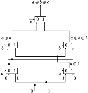
Figure 2:
A realization of the adder function
based on the BDD representation and multiplexers.
Finally, we mention that once the BDD form of a boolean function has
been obtained, a circuit realization of proportional size
is immediate: all that is needed is ``Shannon's switch'' also known as
``multiplexer,''
mux (x,f,g):=`if x then f else g'
=(x Ù f) Ú (x Ù g),
together with entries grounded at 0 and 1.
A diagrammatic representation is as follows:

The way the BDD of the adder function ``compiles'' into a circuit
based on multiplexers is displayed in Figure 2.
2 Polynomial Representations of BDD's
As a preparation for the treatment of synchronous decision diagrams, we
now introduce a representation of boolean functions by means of univariate
polynomials with coefficients in the binary field F2.
Let f be a boolean function in n variables.
Its truth-table polynomial F=Tf is defined as follows:
interpret each n-tuple (x1,x2,...,xm) of boolean values
as the binary representation of an integer,
b(x1,...,xn):=(x1x2... xn)2 =
x12n-1+...+xn,
(observe the convention that lower order bits are on the right), and set
|
T |
f(z)= |
|
f(x1,x2,...,xn)
z |
|
.
|
|
|
| x1x2x3 |
000 |
001 |
010 |
011 |
100 |
101 |
110 |
111 |
| b(x1,x2,x3) |
0 |
1 |
2 |
3 |
4 |
5 |
6 |
7 |
| f(x1,x2,x3) |
0 |
1 |
1 |
0 |
1 |
0 |
0 |
1 |
|
Tf(z)=z+z2+z4+z7.
The BDD algorithm is amenable to interpretation in this formalism.
Define the two ``sectioning'' operators on polynomials F2[z] by
|
S0 |
æ
ç
ç
è |
|
fkzk |
ö
÷
÷
ø |
= |
|
f2kzk,
S1 |
æ
ç
ç
è |
|
fkzk |
ö
÷
÷
ø |
= |
|
f2k+1zk.
|
| S0 T |
( |
f(x1,...,xn-1,xn) |
) |
|
|
| S1 T |
( |
f(x1,...,xn-1,xn) |
) |
|
| = T |
( |
f(x1,...,xn-1,1) |
) |
. |
|
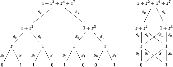
Figure 3:
Polynomial representations of the Binary Decision Tree and
the Binary Decision Diagram of the ternary adder.
3 Synchronous Decision Diagrams
In all generality,
a sequential function maps infinite sequences of binary
inputs into infinite sequences of binary outputs.
It thus takes as input a ``stream'' of bits
(xt)t³0 and produces another ``stream'' (yt)t³0. In
other words, a sequential function is a mapping from B¥ to
B¥. For practical purposes, additional
constraints must clearly be
imposed on the sequential functions considered.
First, we say that a function f from B¥ to B¥ is
causal when the output at time t depends exclusively upon
the input values from times 0 through t. In what follows, only
causal functions are considered. (For the mathematically inclined
reader, we note that causal functions are particular continuous
functions on the set B¥ endowed with the topology induced by
the metric d(a,b)=2-min { t | at¹bt }.)
For f causal, we let ft be the output at time t:
yt=ft(x0,...,xt).
By analogy with the specialization of combinational functions, we
define the predictors, v0 f and v1 f,
by the properties:
(v0 f)t+1=ft(x0,...,xt,0),
(v1 f)t+1=ft(x0,...,xt,1).
These predictors tabulate which value of f will be taken when the
input bit to arrive next is specialized to 0 or 1.
For b0... br a sequence of bits, we then have the
(generalized) predictor of order r+1,
By infinite iteration, we can then construct the
synchronous decision
tree (SDT) denoted by
sdt(f) as the tree where the nodes are the quantities
n=vw(f) and the descendents of
node n are v0(n), v1(n).
The tree sdt(f) can be realized by an infinite tree circuit using
only multiplexers and registers (i.e., circuits capable of storing one
binary value), much
in the same way as combinational circuits are
realized by finite tree circuits. See Figure 4 for an
illustration.
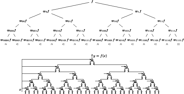
Figure 4:
The infinite synchronous decision
tree (top) and its circuit realization (bottom).
Next, in order to be computable by some physical device, a digital
function must be causal, but also representable by some finite
system.
To formalize this,
we introduce the notion of on-line computable function: by
this is meant a function such that the collection of all predictors of
all orders forms a finite set. In this case, the (infinite) tree can
be converted to a (finite) graph5 by identifying nodes of the SDT associated with
functions that are equal. The resulting graph is called the synchronous decision diagram (SDD) and it is obtained by a simple
algorithm: (i) build the infinite SDT for f;
(ii) systematically share all the subexpressions generated
during
this process. (Optionally, one may also consider functions f, g to be
isomorphic if either f=g or f=¬ g; in that case the SDD will also
involve logical negation gates but will be more compact.)
When presented as above, the SDD algorithm looks like an infinite
process. However, it can be seen [8] that if a function
is realizable by a finite transducer (i.e., an automaton with output),
then the SDD algorithm terminates in finite time. In fact, the SDD
algorithm provides an integrated alternative to the classical design of
sequential circuits.6
In order to illustrate the SDD concept, we apply it now to the design
of a circuit
that takes as input a stream of bits (xt) meant to represent the real
number
x=åt³0xt2-t and produces as output the stream (yt)
where the real number h=åt³0yt2-t satisfies
h=(1/3) x.
Introduce the integers
|
x(t)=2t |
|
|
,
y(t)=2t |
|
|
, t³ 0,
|
x(t)=3y(t)+rt, 0£ rt<3, t³ 0.
An easy calculation that mimics high school arithmetics yields
2rt+xt+1=3yt+1+rt+1, t³ 0.
These formulæ show that the function h=x/3 is causal and
that the bit
yt+1=ft+1(x0,...,xt+1)
depends only on the last input bit together with the ``carry''
rt that is inherited from past history.
The carry can only assume three values and accordingly the
number of predictors is finite, to the effect that
the SDT has only
six nodes. Thus, f is on-line computable. Figure 5
shows the result of the construction.
(In the diagram,
a transition denoted by
a/b is triggered by reading the bit a
and results in producing the bit b.)
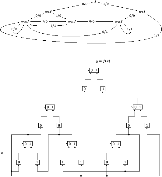
Figure 5:
The `(1/3)
x' function: its abstract SDD
representation (top) and the circuit realization (bottom).
4 Formal Power Series Representations of SDD's
A causal
function f is characterized by its truth table. This
is the power series representation Tf, an
element of F2[[z]] defined as
|
T |
f(z):= |
|
|
ft(x0,...,xt) z |
|
.
|
|
F0F1F2... =
|
[ |
f0(0)f0(1) |
] |
[ |
f1(00)f1(01)f1(10)f1(11) |
] |
[ |
f2(000)f2(001)... f2(111) |
] |
... ;
|
| F(z)= |
[ |
f0(0)+zf0(1) |
] |
+z2 |
[ |
f1(00)+zf1(01)+z2f1(10)+z3f1(11) |
] |
|
| +z6 |
[ |
f2(000)+zf2(001)+···
+z7f2(111) |
] |
+···, |
|
Equipped with these definitions, we observe the action of sections,
|
S0F(z)= |
[ |
f0(0) |
] |
+z |
[ |
f1(00)+zf1(10) |
] |
+z3 |
[ |
f2(000)+zf2(010)+··· +z3f2(110) |
] |
+··· ,
|
|
S1F(z)= |
[ |
f0(1) |
] |
+z |
[ |
f1(01)+zf1(11) |
] |
+z3 |
[ |
f2(001)+zf2(011)+··· +z3f2(111) |
] |
+···,
|
|
S0F(z)= |
|
z |
|
S0Ft(z)=
f0(0)+z |
|
z |
|
S0Ft+1(z),
|
|
S1F(z)= |
|
z |
|
S1Ft(z)=
f0(1)+z |
|
z |
|
S1Ft+1(z).
|
S0(Tf)(z)=f0(0)+zT(v0f)(z),
S1(Tf)(z)=f0(1)+zT(v1f)(z).
Now, by definition,
f is on-line computable when its predictors lie in a
finite set. The equation above shows that this is equivalent
to the finiteness of vector space over F2(z) of all
the (iterated) sections of the truth table.
The connection is thereby established with what is otherwise known as
automatic
series;7 see the foundational paper by Christol
et al. [3], Dumas's thesis [4], and several
summaries in previous issues of the Algorithms Seminar Proceedings.
We state:
Theorem 1 The truth table Tf of an online computable
function f is a 2-automatic series. Consequently, it is an algebraic function
over the field F2(z).
Each causal finite function f may thus be represented by a bivariate
characteristic polynomial P(z,y) so that the truth table Tf is the only root yÎF2[[z]] of P(z,y)=0. Conceivably,
this theorem opens an avenue to circuit design and verification by
means of polynomial elimination algorithms---typically, Gröbner
bases. Given the superexponential complexity of algebraic
elimination, it seems however to the authors of the summary that a
direct approach based on linear algebra (in accordance with standard
techniques of 2-automatic series [4]) should yield decision
procedures of lower complexity.
5 From Circuits to Functions
In this section, we show how to put to
good use the formalism introduced above
in order to analyse circuits:
starting from a given circuits, the goal is to determine a
mathematical specification of what it does.
Note that the dual problem of synthesis
has been already implicitly
tackled on the occasion of the ``one-third'' function
(x|®x/3).
Let us first consider a circuit that takes as input a stream of bits
(gt) and produces the stream (ht)
which is the same stream delayed by 1 in time. In other words, we have
h0=z0 (the initialization value) and ht=gt-1 for t³1.
In the context of a finite circuit, the values ht are
described by their truth table and they depend on the global input
sequence x=(xt)t³0 of the circuit. Thus, in terms of the finite
boolean functions gt(x0,...,xt) and ht(x0,...,xt), we have
h0=z0, ht(x0,...,xt)=gt-1(x0,...,xt-1)
for t³ 1.
This relation translates into a relation between the truth tables of the
input (G) and the output (H) of the register,
|
H(z)=(1+z) |
( |
z0+z2G(z2) |
) |
.
(1) |
Consider next a multiplexer that takes as input two
streams of bits a(x) and b(x) (themselves causal functions of the input
stream x) and assume that control is achieved by the input
stream x.
The output m(x) is a causal function
defined by
|
mt(x0,...,xt)=mux
|
( |
xt,at(x0,...,xt),bt(x0,...,xt) |
) |
,
|
|
m(x)=mux |
( |
x,a(x),b(x) |
) |
.
|
| A |
a0(0) |
a0(1) |
a1(00) |
a1(01) |
a1(10) |
a1(11) |
a2(000) |
a2(001) |
... |
| B |
b0(0) |
b0(1) |
b1(00) |
b1(01) |
b1(10) |
b1(11) |
b2(000) |
b2(001) |
... |
| M |
b0(0) |
a0(1) |
b1(00) |
a1(01) |
b1(10) |
a1(11) |
b2(000) |
a2(001) |
... . |
This relation translates into
M(
z)=(
S0B)(
z2)+
z(
S1A)(
z2),
(2)
which now involves a blend of sectioning and Mahlerian operators.
Now, a finite circuit can be translated into a system of fixed-point
equations: to each entity is associated its truth table;
then relations (1) and (2) (used repeatedly)
provide the system of
equations.
Here is an application to a circuit discussed in [8].
This circuit comprises one inverter (represented by a circle), two
multiplexers, and one
register that is initially set at 0. The upper entry of the leftmost
multiplexer receives a continuous stream of 1's which is represented
by 1.

What is required is to verify that the circuit
computes the function
x |® h=x+1,
where the input and output streams are now interpreted as dyadic numbers,
that is
|
x= |
|
xt 2t,
h = |
|
yt 2t, x,y ÎZ2.
|
| Y(z) |
| = |
æ
ç
ç
è |
S0 |
æ
ç
ç
è |
|
+V |
ö
÷
÷
ø |
ö
÷
÷
ø |
(z2)+z |
( |
S1V |
) |
(z2)
= |
|
+ |
( |
S0V |
) |
(z2)+z |
( |
S1V |
) |
(z2) |
|
| |
|
| V(z) |
=(1+z)z2W(z2), |
| W(z) |
| = |
æ
ç
ç
è |
S0 |
|
ö
÷
÷
ø |
(z2)+z |
( |
S1V |
) |
(z2)
= |
|
+z |
( |
S1V |
) |
(z2). |
|
In order to understand the function computed by the circuit, we proceed
to solve this system.
The second equation provides
S1V(z)=zW(z), a relation that, when carried into the third equation, gives:
Such a functional equation is now easily solved by iteration,
and this form entails in turn
|
| =
|
[ |
1 |
] |
+
z2 |
[ |
z+z2 |
] |
+
z6 |
[ |
z+z3+z5+z6 |
] |
+
z14 |
[ |
z+··· |
] |
+··· . |
|
6 Conclusion
Due to constraints already evoked, we could only scratch the surface
in this brief8 seminar summary. The
point of view developed in the talk bases itself further on the
existence of isomorphisms between various domains. For instance, as we
have seen, the boolean domain may be viewed as B or F2;
boolean functions are representable as elements of F2[z]; on-line
computable functions are equivalent to algebraic elements of
F2[[z]] and to 2-automatic series. There exist several other
interesting connections, for instance, with the ring of dyadic
integers Z2 that form one of the conceptual basis of the original
paper [8]. Such isomorphisms do increase the
expressive power of the SDD formalism that we have opted to develop
here only over B while making use of representations
in F2[[z]].
There is also great practical potential in the algorithms
associated with the SDD concept. Quoting from Vuillemin:
The SDD of f is a cyclic data structure,
which represents the minimal finite state machine for f. In the worst
case, its size is doubly exponential in the size of f.
However, efficient
algorithms exist to operate on the SDD representations
with the following characteristics: constant time9
for
f(l x), f(1+l x); linear time for ¬ f(x),
l f(x), the inverse
g(f(x))=x, and the fixed point y =l g(x,y); quadratic time for
the composition f(g(x)) and for boolean operations, f(x) Ù
f(y),
etc; cubic time for the more general composition f(g(x),h(x)).
The SDD opens an approach to sequential circuit synthesis and
verification whose implementation is straightforward in a high-level
language, and which can cope automatically with synchronous circuits
of limited size.
References
- [1]
-
Bryant (Randal E.). --
Graph-based algorithms for boolean function manipulation. IEEE
Transactions on Computers, vol. C-35, n°8, 1986,
pp. 679--691.
- [2]
-
Bryant (Randal E.). --
Symbolic boolean manipulation with ordered binary decision diagrams.
ACM Computing Surveys, vol. 24, n°3, 1992,
pp. 293--318.
- [3]
-
Christol (G.), Kamae (T.), Mendès France (M.), and Rauzy (G.). --
Suites algébriques, automates et substitutions. Bulletin de la
Société Mathématique de France, vol. 108, n°4,
1980, pp. 401--419.
- [4]
-
Dumas (Philippe). --
Récurrences mahlériennes, suites automatiques, études
asymptotiques. --
Institut National de Recherche en Informatique et en Automatique,
Rocquencourt, 1993, 241p. Thèse, Université de Bordeaux I,
Talence, 1993.
- [5]
-
Flajolet (Philippe), Sipala (Paolo), and Steyaert (Jean-Marc). --
Analytic variations on the common subexpression problem. In Paterson
(M. S.) (editor), Automata, languages and programming. Lecture
Notes in Computer Science, vol. 443, pp. 220--234. --
Springer, New York, 1990. Proceedings of the 17th
ICALP Conference, Warwick, July 1990.
- [6]
-
Liaw (Heh Tyan) and Lin (Chen Shang). --
On the OBDD-representation of general boolean functions. IEEE Transactions on Computers, vol. 41, n°6, 1992,
pp. 661--664.
- [7]
-
van Leeuwen (Jan) (editor). --
Handbook of theoretical computer science. Vol. A. --
Elsevier Science Publishers, Amsterdam, 1990, x+996p.
Algorithms and complexity.
- [8]
-
Vuillemin (Jean E.). --
On circuits and numbers. IEEE Transactions on Computers,
vol. 43, n°8, 1994, pp. 868--879.
- 1
- Editor's Note.
I acknowledge the promptitude of the authors of the summary.
Especially their promptitude to renegociate deadlines.
- 2
- The BDD's described here are sometimes called
OBDD's, where the `O' stands for ``ordered'' and refers
to a fixed ordering on boolean variables.
- 3
- In the worst case, a BDD contains up to O(2n/n)
nodes. A similar bound [6] even holds on average,
for a random boolean function.
Such properties are also related to a famous theorem of Shannon and
Muller [7, p. 763]
to the effect that almost all boolean functions
have minimal circuit complexity of the order of 2n/n.
This theoretical discussion is however to be counterbalanced by
the fact that functions destined to be realized in silicon are seldom
chosen at random!
- 4
- The structure and size of a BDD depends on the ordering of
variables. Several heuristics have been developed in order to try and
come up with
``good'' orders.
- 5
- Observe that, as opposed to the case of combinational
circuits,
the corresponding graph is no longer acyclic since
nodes at
different
levels in the tree may be collapsed.
- 6
- A classical construction starts from a specification of a
finite automaton
and stores the current state of the automaton in binary registers
while realizing the
transition function by means of a combinational circuit (itself
possibly optimized via BDD's).
- 7
- A sequence is defined to be automatic if its nth element is
produced by a finite transducer applied to the binary representation
of n; a series is automatic if its sequence of coefficients is
automatic. Equivalent characterizations of automatic series are
as algebraic elements
over F2(z) or as solutions to Mahlerian equations; refer
to [3, 4].
- 8
- Editor's Note. I wish to express my
true gratitude to the authors of the summary for not exceeding three
times the expected length of a typical summary.
- 9
- Dyadic interpretations (Z2) are understood in the first
two examples.
This document was translated from LATEX by
HEVEA.


